This tool calculates the critical buckling load of a column under various support conditions. Reversely, the tool can take as input the buckling load, and calculate the required column properties. The tool uses the Euler's formula.
Buckling is a catastrophic phenomenon, where a member under compression, suddenly reaches a state of reduced axial stiffness, followed by excessive displacements or rotations of its cross-sections. The phenomenon can also appear in a member under flexure. In this case, part of the cross-section is under compression, which, in certain circumstances, can lead to a lateral buckling phenomenon, with excessive lateral displacements (out of plane). Buckling is not a proportional phenomenon. It is rather a critical one. When compression level is relatively small, the affected member behaves “normally”, with no buckling at all. When compression reaches a critical level though, buckling occurs suddenly. It is remarkable, that buckling is related to the stiffness of the member and not to its strength. Indeed, buckling can appear long before the stresses in the member approach their elastic or yield limit. Ideally, the affected member should return to its perfect initial state, if the compressive load is removed. Nevertheless, buckling is still considered catastrophic, because a buckled member looses its load bearing capacity (due to stiffness drop), off-loading it to other members of the structure, while its displacements can become uncontrollably high. Under these circumstances, the material can quickly exceed its elastic limits, resulting in permanent damages of the affected member. Also, off-loading its load-bearing capacity to other members can lead to a domino type sequence of member failures, resulting in global collapse to the entire structure.
Due to its sudden nature, buckling is considered an undesirable mode of member failure.
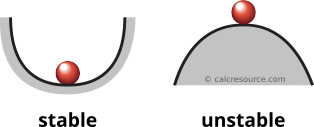
Buckling is often referred to as instability. A system is considered in a stable equilibrium when small perturbations of its initial conditions (e.g. loading) would not cause dramatic changes to its equilibrium solution (e.g deformed shape). This type of equilibrium can be visualized with a ball, resting at the bottom of a valley. On the other hand, the equilibrium of a system is considered unstable, when small perturbations of its initial conditions would result in a dramatically different solution. This type of equilibrium can be visualized with a ball, standing at the top of a hill. In column buckling, when the imposed compressive load approaches a critical level, a small perturbation of the loading can lead the column to depart from its straight shape into a deflected shape, typically of bow form, which is radically different. If the perturbation is removed, the column does not return to its initial straight shape (similarly, the ball does not return to the top of the hill).
Types of equilibrium
Types of buckling
Depending on the cross-section, the loading and the boundary conditions of a member (column, beam, etc) , several different types of buckling may occur. These are commonly classified as:
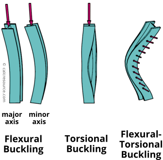
The deformed shape of a member under flexural buckling is similar to a member under flexural bending, hence its name. The cross-sections are deflected without any torsional rotation. If no lateral restraints exist across the member length, the weak axis of the cross-section is deflected. For strong-axis buckling to occur, lateral restraints should prevent weak-axis buckling in the first place. Flexural buckling is common for members under compression, typically columns.
Torsional buckling is less common, and looks like the member is subjected to torsional moments. The cross-sections are rotated around the member longitudinal axis, without any deflection.
Flexural-torsional buckling, is common for slender cross-sections under bending. The cross-sections are deflected laterally (perpendicular to the flexural deflections) while also rotating around the member longitudinal axis.
The following figure illustrates the three buckling types for members.
Member buckling modes
Except for the buckling of entire members, other types of instability can also occur in a structure. When, the compressive stresses in a local area of a member (either beam or column) become critically high, local instabilities may occur, associated with the slenderness of the plates, the cross-section is built from, rather than the member slenderness. These phenomena are classified as local buckling, shear buckling and crippling.
On the other end, instabilities may occur in a structure as a whole, while its individual members remain unbuckled. In this case, the instability is affected by the overall slenderness of an assemblage of members rather than the slenderness of individual members. Typical structures subject to global system buckling are trusses and arcs.
Flexural buckling of columns
Flexural buckling is a mode of instability, affecting members under axial compression. In its buckled state the column has a bow type deflected shape. The following assumptions are made for the analysis herein:
The material is elastic
The cross-section is prismatic (it is constant across the length of the column)
The column has no imperfections. It is perfectly straight and the imposed load is perfectly aligned with its longitudinal axis.
the deformations remain small
the cross sections of the buckled column remain normal to the deflected axis (aka elastic curve).
The last two assumptions are compatible with the Euler-Bernoulli beam theory. The third assumption, is about imperfections, a crucial aspect affecting column buckling. The role of imperfections will be examined later. For the time being it is considered that no imperfections exist.
Equilibrium path of a perfect column
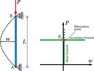
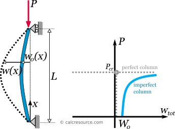
The equilibrium of a perfect column under an axial compressive load can be achieved in two distinctively different ways. Taking as an example the pinned column in the next figure, one of the two ways is for the column to remain straight while its length is shortened under the influence of the axial load. No deflection is recorded in this case. This is the equilibrium path the column prefers to follow, when it starts from an initially straight shape and the imposed load remains relatively small. In a load vs. deflection diagram, this equilibrium mode, is drawn as a straight vertical line, aligned with the axis of , since deflection remains zero for increasing load. After a certain value of axial load, though, this mode of equilibrium becomes unstable. The critical load value is denoted as and the unstable path is indicated in the diagram with a dashed line. Therefore, another mode of equilibrium, becomes preferable, once reaches . This second mode, dictates the column to buckle, with non-zero lateral deflections . Assuming displacements are small, this equilibrium mode provides no stiffness against lateral deflections, and as a result, it is drawn in the diagram as a horizontal line, crossing the load axis at .
Pinned column under axial compressive load and its equilibrium path
The first equilibrium mode, where the column remains straight, is called main branch of the equilibrium path. The second mode, where the column buckles, is called secondary branch of the equilibrium path. The point, where the two branches are met, is called point of bifurcation. At this point of the diagram, the column equilibrium shifts branches abruptly (from the main to the secondary). The axial load , where this shift occurs, is called critical buckling load. The two branches together make the equilibrium path of the column. It is worth to note, that the direction of the deflections (whether they are towards the left or the right side) cannot be predicted mathematically. When the column equilibrium reaches its bifurcation point, one or the other direction will be followed by chance. Also their magnitude cannot be quantified, since the secondary branch is horizontal, which means that deflections can take any arbitrary value (mathematically infinite) once the critical load is reached. This uncertainty results from the assumption we've made, that the column has no imperfections. It will be shown later, that once imperfections are accounted for, the uncertainty is removed and the direction of the deflections can be determined, as well as their magnitude.
Critical buckling load does not necessarily reflect the actual column capacity to carry a compressive axial load. See the section about imperfections, later in this article, to get a grasp on how imperfections play a negative role on load bearing.
Euler's load
The critical buckling load of a column under axial compressive load has been found by Leonhard Euler. For this reason it is commonly referred to as Euler's buckling load (or just Euler's load). Using the assumptions of Euler-Bernoulli beam theory and neglecting any imperfections, the following formula was derived, that defines the critical buckling load of a column:
where:
,
L, the length of the column,
K, a factor called effective length factor, dependent on the boundary conditions of the column (i.e. its supports),
E, the modulus of elasticity,
I, the cross section moment or inertia (second moment of area).
The length is called effective buckling length, and because it is squared in the formula, it becomes the most influential parameter for the critical buckling load. The higher the effective length, the lower the resulting load. The other parameter affecting Euler's load is the flexural rigidity of the column cross-section . We observe that critical buckling load is proportionally affected by flexural rigidity.
End supports
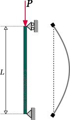
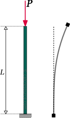
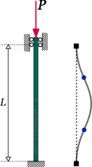
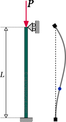
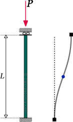
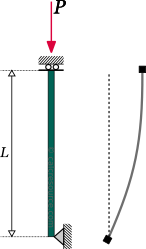
The end supports of the column influence the Euler's load through the effective length factor . Specifically, the more redundant the column is in terms of supports, the lower the factor becomes, resulting in a higher critical load. Theoretically, the effective length is defined as the distance it takes for the buckled column shape to complete a bow of deflection (half sine). The following table displays the theoretical values of as well as the critical buckling load and the deflected column shape, for various common support conditions. Note that for design purposes increased values of the effective length factor may apply, resulting to reduced critical loads. Also take in mind that the presented shape function in the table, provides only the shape and not the actual magnitude of deflections.
Column flexural buckling with various end supports
End supports
Effective
length
factor,
Critical
buckling
load,
Deflected
shape function1,
(x=0 at the bottom)
1
2
0.5
0.7
()
1
2
1 provides the shape and not the actual magnitude of deflections
Proof of Euler's formula
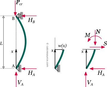
The Euler's critical buckling load can be derived if the equilibrium of the column is examined at the buckled state. At this state the imposed axial load has become equal to . Let's take as an example a column with two pinned supports, as shown in the next figure. The reaction forces can be found easily, using the equilibrium equations alone, since the structure is determinant. They are:
A section cut is done at a random distance from the bottom, in the deflected column geometry. The deflection at x is and the resultants are: , the axial force, , the shear force, and the bending moment. The free body diagram of the cut column is drawn at the right side of the figure.
Equilibrium equations of the cut part become:
According to the Euler-Bernoulli beam theory, deflections are related to the bending moments through the formula:
where is the second derivative of . Substituting to the last of the three equilibrium equations we get:
where .
So, the equilibrium at the buckled state, has lead us to a second order differential equation. It is homogeneous because its right side is zero and therefore only the general solution is required. This is:
This solution reveals that the buckled column shape should be a harmonic function of x. Parameters can be determined, taking into account the boundary conditions of the problem. In other words, the deflections at the two end supports. At the lower end, it is x=0, and the deflection should be zero:
Similarly, at the top end of the column, where x=L, the deflection should be zero too:
In order to have a non-trivial solution it must be: , which becomes true if:
or:
Because the last equation is rewritten:
Setting we get the critical buckling load and the column deflections for the first buckling mode:
Parameter cannot be determined. This means that the exact magnitude of deflections remains unknown. What we have found though is their shape.
Higher buckling modes
If we set to a value higher than 1, then we'll get a higher buckling mode. The following table illustrates the 3 first buckling modes, together with the buckling load and the corresponding shape function:
Higher buckling modes feature larger buckling loads. As a result, the column cannot buckle according to a higher mode because it is unable to approach the required critical load. Before doing so, it will buckle with the first mode, which features a lower load. However, if the lateral deflections are prevented at a point of the column (e.g. at mid-length for the pinned column), then the first buckling mode is prevented altogether. This way, the column surpasses the first buckling load and will not buckle unless it reaches the second one. As seen from the deflected shape, the second mode features zero deflection at mid-length (for the pinned column that is) and any lateral restraint at this point becomes indifferent. It will not prevent the column from buckling with the second mode, and the column will just do so. Similarly, if the deflections are restrained at more points across the column length, the second buckling mode will be prevented too, which would force the column to buckle with the third mode, increasing the critical load even more.
From another perspective, it can be seen that a column that buckles with a higher buckling mode, employs a reduced buckling length . For example, under the second buckling mode, of the pinned column, two half sines occur along the column length. For this reason we could consider that:
For the pinned column, we are looking into, this effective length coincides with the unrestrained column length, which is the distance between two supports or lateral restraints.
Using this value of , we get the same critical load, as we get by setting (and using the entire column length ):
The result is identical, however the perspective is different. Thinking in terms of buckling modes is more mathematical in nature.
Lateral restraints
Lateral restraints are a quite effective way to increase the critical buckling load of a column. It can be observed from the previous table that the second buckling mode for the pinned column occurs at a four times bigger critical load, which is a dramatic change. Even more, lateral restraints is a convenient measure to implement, in most cases. Indeed, column length is mostly dictated by other requirements. A change of the column cross-section is an effective measure, but requires much more material for the same increase of the critical load and therefore it can get more costly.
Lateral restraints is a quite effective way to increase the critical buckling load of a column.
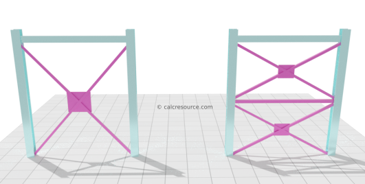
Lateral restraints need to prevent deflections. A common way to achieve that, is bracing. Bracing can take many forms, but the X shaped ones are considered the more effective. The next figure illustrates a bay in a frame structure with two bracing systems. Both affect buckling, however the second one in a much better way. The first one, restraints deflections at the top of the columns, which is still beneficial because otherwise, the columns would be susceptible to sway buckling, which is worst. The second one, though, restraints lateral deflections, both at the top and the middle of the columns. This way, both sway buckling and the first buckling mode are prevented, resulting in higher critical buckling load.
Column bracing in a frame structure, providing lateral restraints against weak axis buckling
The effectiveness of bracing can be limited though, once strong axis buckling becomes critical. For example, the bracing in the last figure prevents deflections when weak column axis buckles, but it is totally ineffective for the buckling of the strong axis (that is when the column deflects in a perpendicular to the screen direction). Therefore, if the weak axis is restrained sufficiently, the critical load for weak axis buckling could surpass that of the strong axis. In that case, providing more lateral restraints, to increase weak axis buckling load, becomes useless.
Imperfections
Imperfections are inherent in any structure that leaves the drawing board and gets constructed. Normally, their effect in the static response of the structure can be neglected. However when stability is accounted for, imperfections become important. First let's look into the types of imperfections that may appear in a column, under compressive load:
Geometrical imperfections. The column is not perfectly straight neither absolutely vertical. Steel columns may have a slightly curved shape (bow imperfection).
Loading imperfections. The compressive load is not aligned with the column axis. In most cases, a load eccentricity is present. Also, a transverse loading component can appear.
Material imperfections. No material is ideally isotropic, homogeneous and linear-elastic. Residual stresses are common in steel sections. In other words, the modulus of elasticity E is not constant over the entire column volume.
End support imperfections. The end supports don't provide reactions perfectly aligned with the column longitudinal axis. Also unaccounted reaction components may be present.
Column with bow imperfection
First, let's examine the case of a pinned column with an initial bow imperfection, described by a half sine function:
Pinned column with bow imperfection under axial compressive load and its equilibrium path
The additional deflection, when an axial compressive load is imposed, is . The equilibrium at this state, adopting the Euler-Bernoulli beam theory, leads to the following differential equation (see section “Proof of Euler's formula” for details of the procedure):
The differential equation is of 2nd order and non-homogeneous. The general solution is a sum of the homogeneous solution (related to the perfect column) and a particular one. Without going into much detail, the following formula is derived for the additional column deflection, after applying the boundary conditions of the problem (zero deflection at both ends):
where , the column Euler's load.
The solution has a half sine shape, similar to the perfect column case. Contrary to the perfect column, though, there is no uncertainty in determining the magnitude of deflections. All the parameters in the above formula can be determined, depending on the problem at hand. For example, the maximum deflection at the middle of the column is:
The plot of the total deflection at column mid-length, , against the imposed load , appears in the previous figure, with a blue line. This is the equilibrium path of the column. It is continuous curve, with a single branch and no point of bifurcation. At zero load, the total deflection is equal to , the imperfection magnitude. Also there is no uncertainty regarding the direction of deflections. These occur towards the side of the bow imperfection. The curve approaches asymptotically to the critical load , for large values of . For practical ranges of acceptable , however, the load given by the solution is reduced compared to the perfect column. For example, if we assume an acceptable deflection , at the middle of the column, equal to 5% of its length, and an initial bow imperfection, with magnitude , we get the following value for the column load:
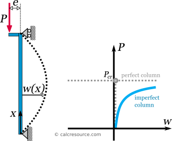
Column with load eccentricity
As a second example, let's examine a column with load eccentricity , as shown in the following figure.
Pinned column under axial compressive load with eccentricity and its equilibrium path
The equilibrium at this state, adopting the Euler-Bernoulli beam theory, leads to the following differential equation (see section “Proof of Euler's formula” for details of the procedure):
Again, the differential equation is of 2nd order and non-homogeneous.The following formula is derived for the column deflection, after applying the boundary conditions of the problem (zero deflection at both ends):
where .
Likewise the bow-imperfection case, there is no uncertainty in determining the magnitude of deflections. For example, the maximum deflection at the middle of the column can be found by setting . The following formula is derived:
The plot of the deflection at the column mid-length , against the imposed load , appears in the last figure, with a blue line. This is the equilibrium path of the column. It is again a continuous curve, asymptotically approaching for high values of deflection. For practical ranges of , however, a reduced load is given by the solution, compared to the perfect column. For example, if we assume an acceptable deflection , at the middle of the column, equal to 5% of its length, and an eccentricity, equal to , we get the following value for the column load:
General remarks on the influence of imperfections
The following points summarize the influence the imperfections normally have on the response of a column under axial compression:
The column load bearing capacity is reduced when imperfections are accounted for (compared to the critical buckling load of a perfect column).
Bigger imperfections cause bigger reductions to the load bearing capacity.
The equilibrium path is a single continuous curve, when imperfections are accounted for. No bifurcation point and no separate branches are introduced.
Deflections can be determined, when imperfections are accounted for. Also their direction is not uncertain.
The response in non-linear from the start.
When designing an actual column, susceptible to buckling, imperfections should always be accounted for. It is not safe to neglect them.
Examples
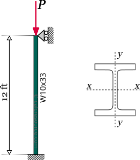
Column buckling with simple supports
Find the critical buckling load of a 12 ft long, steel column, having a W10x30 profile section. The column is fixed at the bottom and pinned at the top, without any lateral restraints. Given is the steel modulus of elasticity and the W-section moments of inertia and .
Solution
We assume, from the lack of any special mentioning, that supports are the same towards any horizontal direction. Also, the column is not laterally restrained. Therefore, the column should have identical effective buckling lengths, either for strong axis or weak axis buckling. However, because weak axis buckling occurs at a lower load level, it will be the critical one for the column. We need to examine only weak axis, as a result.
Effective length is given by:
Effective length factor , for a column with one fixed and one pinned support is equal to 0.7 (see table in a previous section):
Therefore:
We now use the Euler's formula to find the critical load for weak axis buckling:
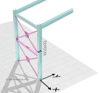
Buckling of column in a 3D frame
Find the critical buckling load of a 12 ft long, steel column, in the following 3D frame, having a W10x33 profile section. The column is fixed at the ground, towards all directions. At the top, the column is pinned for deflections towards the x axis and guided (fixed rotations, free deflections) for deflections towards y direction.
Given is the steel modulus of elasticity and the W-section moments of inertia and .
The column features different support conditions towards each axis. It is not obvious which one could give us the lower buckling load. Therefore, both of them should be examined.
Strong axis buckling
The following conditions apply for strong axis buckling:
Fixed support at the ground
Guided support at top
No lateral restraints
Effective length factor , for these end supports is equal to 1.0:
Therefore:
Using Euler's formula we find the critical load for strong axis buckling:
Weak axis buckling
The following conditions apply for weak axis buckling:
Fixed support at the ground
Pinned support at top
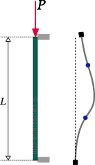
Lateral restraints at top and mid-length
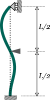
Under these conditions, the column buckling shape should look like the following:
Effective length is the length of half a sine in the buckled shape. There are two half sines though, one at the upper part of the column and another at the bottom. We should select the larger of the two, because the longer the effective length the lower the buckling load. This would be the upper part, which takes half of the column length to deflect with a half sine shape (while for the lower part, the length is 0.7L/2=0.35L).
Therefore:
Using Euler's formula we find the critical load for weak axis buckling:
Conclusion
The critical buckling load of the column will be the lower of the two. This is the one for weak axis buckling:
It should be noted that the two buckling loads are not very different. This indicates a good design.