
Support reactions of a simply supported beam
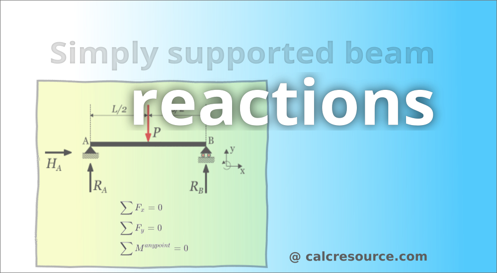
Table of contents
Introduction
The simply supported beam is one of the most simple structures. It features only two supports, one at each end. One is a pinned support and the other is a roller support. With this configuration, the beam is inhibited from any vertical movement at both ends whereas it is allowed to rotate freely. Due to the roller support it is also allowed to expand or contract axially, though free horizontal movement is prevented by the other support.
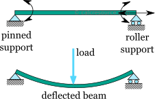
Removing any of the supports inserting an internal hinge, would render the simply supported beam to a mechanism, that is body the moves without restriction in one or more directions. Obviously this is unwanted for a load carrying structure. Therefore, the simply supported beam offers no redundancy in terms of supports, and if a local failure occurs the whole structure would collapse. These type of structures that offer no redundancy are called critical or determinant structures. To the contrary, a structure that features more supports than required to restrict its free movements is called redundant or indeterminate structure.
Static analysis - how to find reactions
Since a simply supported beam is a determinate structure, it is possible to obtain its static response using just equilibrium equations. These equations enforce that the sum of all forces and moments, acting upon the structure, in any direction, including both applied loads and support reactions, must be zero. For a plane structure, with in plane loading, the equilibrium equations are:
The first two equations, enforce force equilibrium in directions x and y, (a Cartesian system of axes that can be arbitrarily defined, depending on the case). The third equation enforces the equilibrium of all moments around a certain point, which can be any point of the plane.
Example 1: support reactions of a simply supported beam with a point load
Determine the support reactions of a centrally loaded simply supported beam, with a point force , at the middle
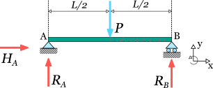
Assigning the unknown support reactions to variables , and , as shown in the figure, the three equilibrium equations are defined this way:
- Along direction x, there is no imposed force applied to the structure. There is only the unknown support reaction . Thus the first equilibrium equation is:
- Along direction y, the imposed force P is applied to the center of the beam, as well as support reactions and . Thus the first equilibrium equation is:
- For the third equation we have to choose one point around which the moments are calculated. It is often more convenient to select a point through which some of the forces are directed (such as point A in our example), because, the resulting moments for these forces would be zero. So, around point A, support reactions and have no lever arm, imposed force have a lever arm equal to half the beam length and support reaction have a lever arm equal to the beam length. Assuming counter-clockwise positive rotation, the third equation becomes:
There are three unknowns, and we have three equations, therefore it is possible to solve the system of equations and obtain the unknown support reactions. is directly found from the first equation equal to zero. Unless there is an imposed load along the beam longitudinal axis, this reaction will always be zero. From the third equation we can directly obtain :
And finally, substituting to the second equation, should be found too:
When the imposed load is a distributed one, the procedure remains the same, provided that you replace it with an equivalent point force, having:
- same direction
- magnitude equal to the total force of the distributed load
- application point at the centroid of the distributed load
Example 2: support reactions of a simply supported beam with distributed load
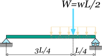
Find the reactions of the following simply supported beam, with a uniform distributed load applied to its half span.
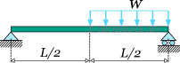
Before proceeding to the equilibrium equations, we will replace the distributed load with an equivalent point force . This force should have the same downward direction and a magnitude equal to the total load, that is . Its application point should be located at the centroid of the distributed load it replaces, in this case one quarter length from the right end of the beam. The following figure illustrates the beam, with the equivalent load we are going to use, for the needs of equilibrium.
Next we assign the unknown support reactions to variables , and , and we define the x, y axes as shown in the figure below.
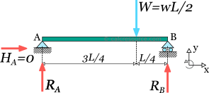
Because there there is no horizontal component of imposed loads, reaction should be zero, by virtue of the equilibrium equation . The remaining two non-trivial equilibrium equations, are written below, taken into account the positive directions, indicated by our axes system:
From the last equation we can find :
Substituting to the first equation, we can find the remaining unknown reaction :